
Kruchten’s “4+1” View Model (for Dummies)
Kruchten's "4+1" model uses multiple views to describe a software-intensive system's architecture, in line with the IEEE 1471-2000 standard. Learn how it works.
Kruchten’s “4+1” model is a view model [1] designed by professor Philippe Kruchten that fits the “IEEE 1471-2000” standard (Recommended Practice for Architecture Description of Software-Intensive Systems [5]), which is used to describe the architecture of a software-intensive system based on multiple viewpoints.

Photo of Philippe Kruchten
Okay, if you haven’t understood anything so far and you’re not in your 3rd or 4th year of a Software Engineering degree (or similar), don’t worry, that’s normal. And if you are in your 3rd or 4th year and still haven’t understood anything, get your act together NOW! Because these things should (at least) ring a bell.
Well, let’s go step by step. Before explaining Kruchten’s model in more detail, let’s explain and try to make a few concepts clear, such as what a software system is, what a view is and what a viewpoint is.
First, let’s find out what “a software system” is, which we define with the following “equation” (made in jarroba.com).
Software system = Hardware + Software
Indeed, broadly speaking, a software system is software (more or less complex) that “runs” on a given piece of hardware (more or less complex). For example, the whole deal with “ATMs” is a software system, since on a “hardware” that we call an “ATM”, some kind of program (software) runs that lets us carry out certain transactions.
Another thing this Kruchten model talks about is the concepts of view and viewpoint. Well, a view is nothing more than a representation of the whole software system from a given perspective, and a viewpoint is defined as a set of rules (or conventions) for creating and understanding views.
Okay, if it’s still not very clear what views and viewpoints are, let’s explain it with a simple analogy from the world of architecture (the architecture of houses, buildings and so on):
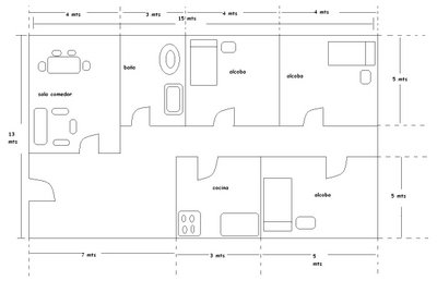
If an architect shows us a floor plan of a house (like the one in the following image), they are showing us a view of the house. Since we have no idea about architecture, when they explain to us, or give us a document explaining, that a certain symbol in the plan represents a door or another symbol represents a table, they are giving us a viewpoint so that we can understand the floor plan. If later they showed us another plan (or a scale model) of the house, they would be giving us another view of the house and would have to explain the new viewpoint, that is, they would have to explain what each symbol or object in that new view means.
Well then, now that we’ve seen what views and viewpoints are, and having explained what a software system is, you can already get an idea of what Kruchten’s “4+1” view model for describing software system architectures is about, right?
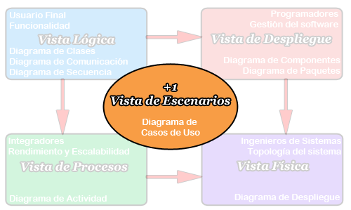
Well, yes. What Kruchten proposes is that a software system should be documented and presented (as proposed in the IEEE 1471-2000 standard) with 4 clearly distinct views, and these 4 views must be tied together by one more view, the so-called “+1” view. Kruchten named these 4 views: logical view, process view, deployment view and physical view, and the “+1” view, whose job is to relate the 4 views mentioned, he named the scenario view.
Each of these views must show the whole architecture of the software system being documented, but each one must be documented differently and must show different aspects of the software system. Next, we explain what information the documentation of each of these views should contain.
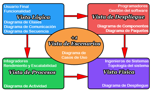
Logical View: This view represents the functionality the system will provide to end users. That is, it must represent what the system should do, and the functions and services it offers. To complete the documentation of this view you can include UML class, communication or sequence diagrams.
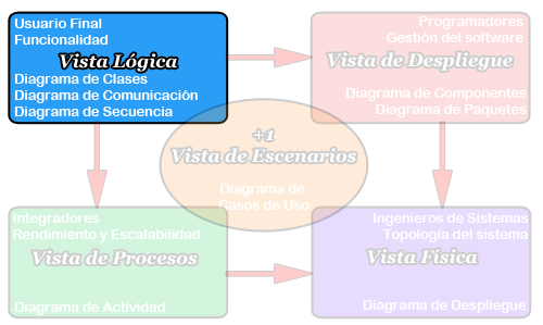
Deployment View: This view shows the system from the perspective of a developer and deals with software management; in other words, it shows how the software system is divided into components and the dependencies between those components. To complete the documentation of this view you can include UML component and package diagrams.
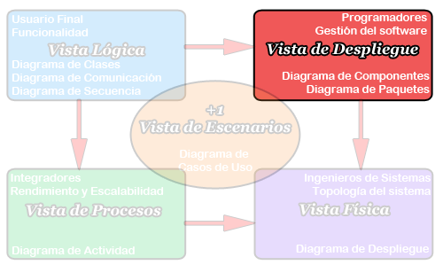
Process View: This view shows the processes in the system and the way these processes communicate; that is, it represents, from the perspective of a systems integrator, the step-by-step business and operational workflow of the components that make up the system. To complete the documentation of this view you can include the UML activity diagram.
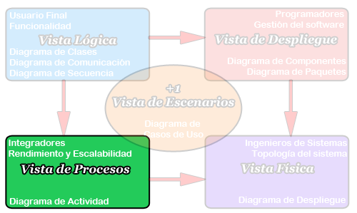
Physical View: This view shows, from the perspective of a systems engineer, all the physical components of the system as well as the physical connections between the components that make up the solution (including services). To complete the documentation of this view you can include the UML deployment diagram.
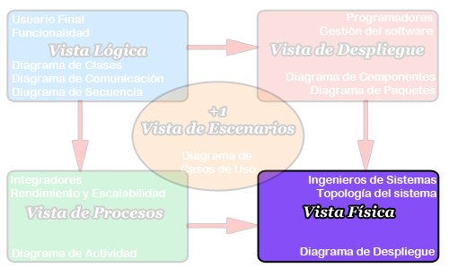
“+1” Scenario View: This view is represented by the software use cases and its job is to join and relate the other 4 views. This means that from a use case we can see how the other 4 views are linked together, giving us traceability of components, classes, machines, packages, etc. needed to carry out each use case. To complete the documentation of this view you can include UML use case diagrams.
Note
VERY IMPORTANT NOTE: Let’s be clear: Kruchten does not say how each view must be documented; he says what has to be documented in each view. That is, when we say the logical view can be documented graphically with a UML class diagram, it doesn’t mean the view has to be documented with that diagram, but that this diagram (because of its characteristics) can document that view.
Kruchten doesn’t define “viewpoints” anywhere for creating views; he only defines the information each view must contain. The thing is that nowadays a lot of software is built under the object-oriented programming paradigm. And as it happens, there is something called UML (Unified Modeling Language) that, how about that, represents views with diagrams made up of “symbols” belonging to a LANGUAGE called UML (UML is a language, not a methodology) that every software engineer knows (or should know). And what does that mean? That a diagram is a view, with a viewpoint that is already very well defined in UML. See, now things are starting to add up!! So there you go: with UML we save ourselves from having to document the viewpoints, since they’re already documented.
And another very important thing is that everyone can represent the views “however they want” as long as they are reflected in the viewpoint, as will happen in many cases with the physical view.
Once we’ve explained the views Kruchten proposes and how to document them, you can see that it’s a pretty good model for documenting the architecture of a “complex” software system, since all the “stakeholders” (people interested in the project, from the system’s user to the company’s big boss) can understand the software system being developed from different perspectives.
To finish, I just recommend using this Kruchten “4+1” view model to document software system architectures following the “IEEE 1471-2000” standard.
Bibliography
[1] Article by Philippe Kruchten “Architectual Blueprints – the “4+1” View Model of Software Architecture“: Architectural Blueprints—The "4+1" View Model of Software Architecture
[2] Wikipedia: http://en.wikipedia.org/wiki/4%2B1_Architectural_View_Model
[3] “Software Engineering: Principles and Practice“, 3rd Edition by Hans van Vliet. May 2008.
“Kruchten’s “4+1” View Model (for Dummies)” by Ricardo Moya at jarroba.com, licensed under Creative Commons Attribution-NonCommercial-ShareAlike 3.0. Registered at Safe Creative.

You may also like

How to Adopt AI in Your Organization Without Making the Most Common Mistakes
Failure and success patterns in AI adoption, a practical decision framework, safe use cases, and minimum viable governance for development teams.

The Real Cost of AI: From the Democratic Promise to the Enterprise Model
Copilot moves to token billing, JetBrains cuts quotas, Claude raises costs with new tokenizer. Analysis of the economic divide AI is opening in 2026.
Leave a comment